Connecting Google Cloud IoT and AVR-IoT WG Eval Board

By Greg Toth for Mouser Electronics
The Microchip AC164160 AVR-IoT WG Evaluation Board is an Internet of Things (IoT) development kit for prototyping
IoT applications that securely connect to the cloud. In this project, we’ll set up an IoT development
environment and configure the AVR-IoT WG board and Google Cloud to run an application that reads hardware sensors
and securely transmits real-time data to the cloud. The AVR-IoT WG board contains a cryptographic coprocessor that
stores and protects the board’s private key that authenticates itself in the Google Cloud. Once sensor data is
sent to the cloud, the data can be stored, processed, and analyzed using a variety of cloud computing resources. As
you perform this project, we’ll show you how to modify and rebuild the application software to make your own
changes. This process will provide a foundation for prototyping other types of secure IoT applications.
Project Materials and Resources
The project bill of materials (BOM) lists components for this project. Additional hardware and software development
tools are also identified.
Project BOM
Hardware
- 11 b/g/n Wi-Fi® access point with a Dynamic Host Configuration Protocol (DHCP) server and
Internet connectivity, without a firewall or proxy that blocks outgoing traffic to the Internet
- Personal computer (PC) running Microsoft Windows
Accounts and Software
- Web browser for accessing software download sites and the Google Cloud Platform
- Atmel Studio 7
- Atmel START tool for selecting and configuring embedded software components
- Login account on the Google Cloud Platform
- Gcloud command-line tool
- Python®
- Serial terminal program, such as Tera Term
- Wi-Fi access point connection details, including a service set identifier (SSID) and security credentials
Project Technology Overview
AC164160 AVR-IoT WG Evaluation Board
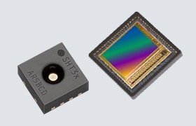
The AC164160 AVR-IoT WG (Figure 1) is a development board from Microchip that tests and evaluates
the ATmega4808 low-power microcontroller and ATECC608A cryptographic coprocessor along with sensors and a Wi-Fi
communications module. It allows developers to prototype IoT applications that securely connect to cloud computing
services through the Internet and that support hardware-based security services for authentication, confidentiality,
and data integrity. To find more detailed information about the board, click here.
Figure 1: Microchip AC164160 AVR-IoT WG Evaluation Board
(https://mouser.com/images/microchiptechnology/hd/AC164160_SPL_t.jpg)
The board contains several onboard resources that make it ideally suited to prototyping secure IoT designs:
- ATmega4808 microcontroller with 48KB of flash and 6KB of random-access memory (RAM)
- ATECC608A cryptographic coprocessor with protected hardware storage for up to 16 keys, certificates, or
sensitive data items
- Wi-Fi® wireless module supporting 802.11 b/g/n
- Digital temperature sensor
- Light sensor
- Lithium polymer (Li-Po) battery charger
- Two push-buttons and four light-emitting diode (LED) indicators
- USB connector
- mikroBUSä expansion connector
- On-board Nano Embedded Debugger (nEDBG)/programmer, serial port, and mass storage interface
Multiple integrated development environments (IDEs) support the AC164160 AVR-IoT WG board including the Atmel
Studio 7 (for Windows®), the MPLAB® X IDE (for Windows®, Mac
OS®, and Linux®), and others. The board connects to a PC using a USB cable, which
supports programming and debugging from the IDE, drag-and-drop programming, and microcontroller serial port
connectivity.
The mikroBUS expansion connector allows you to expand the board’s capabilities with 450+ sensors and
actuators offered by Mikroe through their growing portfolio of Click boardsä.
ATECC608A Cryptographic Coprocessor
The ATECC608A is a high-security cryptographic device that combines hardware-based key storage with hardware
cryptographic accelerators to implement various authentication and encryption protocols. It has an electrically
erasable programmable read-only memory (EEPROM) array that can store up to 16 keys, certificates, or other sensitive
data with configurable access controls and locking functions to prevent changes. It can generate and store random
private keys internally to ensure a private key is not discoverable outside of the device. Each device has a
guaranteed unique 72-bit serial number and its hardware cryptographic accelerators can implement cryptographic
operations’ orders of magnitude faster than software running on a standard microcontroller. To find more
information about this chip, click here.
For this project, we’ll use the private key stored in the ATECC608A to authenticate the AVR-IoT board in the
Google Cloud IoT (This process eliminates all need to handle or store a private key among the board’s software
or configuration data.). Each AVR-IoT board will have a unique ATECC608A with its own set of public and private
keys.
Atmel Studio 7
Firmware programs that run on microcontrollers are typically developed and tested using an IDE—such as Atmel
Studio 7—running on a PC. The IDE provides an editor, compiler, linker, debugger, and a mechanism for
transferring binary program images to a microcontroller.
The AVR-IoT WG board is programmable using several different IDEs including two that are available from Microchip.
For this project, we’ll use the free Atmel Studio 7 IDE that runs on Windows. It supports the full range of
Microchip AVR® and SAM microcontrollers and is available through the Microchip Atmel Studio 7 web page.
Atmel Studio 7 supports the nEDBG debugger interface built into the AVR-IoT WG board. The debugging interface
allows compiled programs to be downloaded and executed with debugging support for breakpoints and memory inspection.
Atmel START
Atmel START is a free tool available by Microchip on the Atmel
START web page. It consists of example projects and libraries you can browse and select to generate your own
source code projects. The purpose of this tool is to quickly create new projects containing necessary functions and
libraries to connect the AVR-IoT WG board to the Google Cloud IoT through the Internet. The libraries interact with
the ATECC608A cryptographic coprocessor, the Wi-Fi module, and the onboard sensors and LEDs. They also implement
communication and security protocols including Transport Layer Security (TLS), Message Queue Telemetry Transport
(MQTT), and JavaScript Object Notation [JSON] Web Tokens (JWT), which Google Cloud employs.
Google Cloud Platform and Google IoT Core
Google Cloud Platform is a collection of computing services and tools that run in Google data centers located
throughout the world. The platform provides a large set of services that can be useful building-blocks to create a
variety of applications using a pay-as-you-go billing model. Cloud services include computing, storage, database
management, networking, monitoring, containerization, mapping, data analytics, pub/sub, machine learning, and IoT.
We’ll use Google’s Cloud IoT Core service to integrate our board with the Google Cloud.
Wi-Fi Access Point
The AVR-IoT WG board contains a built-in Wi-Fi module that connects to the Internet through a Wi-Fi access point
supporting 802.11 b/g/n standards. The access point must supply a DHCP Internet Protocol (IP) address to the Wi-Fi
module and allow outgoing Internet traffic without blocks by a proxy or firewall.
gcloud
The gcloud command-line interface is a tool for
interacting with Google Cloud from the command line of a PC. The tool is available as part of the Google Cloud SDK;
for more information, click here. We’ll use gcloud to display
real-time data the Google Cloud IoT receives.
The Setup (Hardware)
While setting up the hardware, be sure to remember that electronic components are static-sensitive, so handle them
with care.
PC
Power up your PC and allow it to boot up.
Wi-Fi Access Point
Make sure your Wi-Fi access point is running with an active connection to the Internet and with a DHCP server that
assigns IP addresses. You’ll need to know the access point SSID, security type, and security credentials for
use later when configuring the board’s Wi-Fi module.
AC164160 AVR-IoT WG Evaluation Board
Remove the board from its packaging and place it on a suitable work surface. Using the Type-A to Micro-B USB cable,
connect the Micro-B end to the board’s Micro-B USB connector. Connect the other end to the PC. When the cable
is connected, the board will power up and you should see LED activity. You should also see a USB drive named
CURIOSITY appear on the PC. Open the CURIOSITY drive and double-click the CLICK-ME.HTM file. This
takes you to the Microchip Google Cloud microsite where you can generate a Wi-Fi credential file for the board and
test its connectivity.
Scroll down the page and look for the Wireless Network Connection section. In the Wireless Network Name field type
in the Wi-Fi access point SSID, select the network security type, and enter the password (if applicable). Note that
the Wi-Fi SSID and password are currently limited to a maximum of 19 characters. Click the Download
Configuration button which will download a file named WIFI.CFG. Drag and drop that file onto the
CURIOSITY drive to load the Wi-Fi credentials into the board. Look for this LED activity on the board:
- Blue LED (for Wi-Fi connected)
- Green LED (for successful connection to Microchip’s Google Cloud IoT sandbox)
- Yellow flashing LED (for data transmissions to the Google Cloud)
- Note: Red LED (for errors in the Wi-Fi or Google Cloud connection process)
The microsite web page should show real-time graphs of temperature and light readings from the board
(Figure 2). The Microchip sandbox already has the AVR-IoT board authentication credentials
preregistered, so it can work immediately out-of-the-box. Later, we’ll reconfigure the board to connect to our
own Google Cloud IoT instance.
Figure 2: AVR-IoT WG’s Successful Connection to Microchip’s Google
Cloud Quick-Start
The Setup (Software)
Atmel Studio 7
In this step, we’ll download and install Atmel Studio 7 on a Windows PC. First, web browse to the Atmel Studio 7 website, and
look for the Downloads section. Click either the web installer (small file size)
or offline installer (large file size) to download the installation executable. The web installer
is a small program that requires an active Internet connection during the installation, and the offline installer is
the complete installation package. Download the chosen installer, run it, and complete the steps in the installation
wizard. Make sure AVR 8-bit MCU is check-marked in the architecture selection step. You can also
enable the AVR 32-bit MCU, SMART ARM MCU, and Atmel Software Framework and
Example Projects, if you like; however, they aren’t required for this board, and they require
additional disk space. Complete each step in the installation.
After the installation is complete, launch Atmel Studio 7, and you should see the Start Page (Figure
3). Your installation may have additional menu items if you installed the optional components.
Figure 3: Atmel Studio 7 Start Page
While Atmel Studio is open and showing the Start Page, unplug the USB cable connected to the AVR-IoT WG board, wait
a few seconds, then re-insert the USB cable. A second page should appear in Atmel Studio (Figure 4)
with information about the board and additional details available by clicking Kit Details.
Figure 4: Initial AVR-IoT WG Page in Atmel Studio 7
Click the “Update board database” link in the bottom-left to obtain additional
information about the board (requires Internet connection), then unplug the USB cable, wait a few seconds, and plug
it back in. Afterwards, you should see additional information (Figure 5) including a variety of
board-related technical documents.
Figure 5: AVR-IoT WG Page after Updating the Board Database and Reconnecting
the Board
Update Device Pack for ATmega4808
Navigate to Tools > Device Pack Manager and click Check for Updates. In the
search box, type 4808, and press Enter. Look through the list of updates (if any)
to see if any apply to the ATmega4808. Note that the descriptions may not fully spell out “ATmega4808,”
so you must look carefully for anything that applies to ATmega4808. If an update is available, click the
Install button to install the update, then restart Atmel Studio if prompted.
Atmel START
Next, we’ll create a new project for Atmel Studio using the Atmel START tool. On the AVR-IoT WG page
(Figure 5), click “Atmel START example projects using this
board…” This option will launch a web browser and navigate to the Atmel START page for the
board (Figure 6).
Figure 6: Atmel START Page for the AVR-IoT WG Board
Click AVR IoT WG Sensor Node to select that project, and then click Open Selected
Example. Atmel START will assemble a set of code components and then show a project configuration page
where default parameters are customizable (Figure 7). We won’t modify the parameters here, so
click the browser’s Back button to return to the Atmel START page for AVR-IoT WG (Figure 6)
and click Yes (if necessary) to confirm that settings may be lost. If you have trouble returning to
the correct AVR-IoT WG page, just close the browser and start over from the Atmel Studio AVR-IoT WG page
(Figure 5).
Figure 7: Atmel START Default Configuration Parameters for the Generated Code
Project
Download the Project
Click AVR IoT WG Sensor Node (Figure 6), and then click Download Selected
Example. The download file is named AVR IoT WG Sensor Node.atzip, and the .atzip
extension means it’s an Atmel Studio project file. Double-click the downloaded AVR IoT WG Sensor
Node.atzip file to open it in Atmel Studio. You’ll see a project import window (Figure
8) with default names and directory locations filled in. Click OK to complete the
import.
Figure 8: Importing the Atmel START Project into Atmel Studio
If you get a warning messages about necessary device updates, it may be because there are Device Pack updates you
haven’t installed yet.
After the project is imported, it will appear in the Solution Explorer pane (Figure 9).
Figure 9: Solution Explorer Appears After Importing the Atmel START
Project
Verify Building the Project Code
Try building the project “as is” by using the Build > Build Solution menu command.
The project should build without any errors. Note that the current code does generate a few build warnings.
We’ll come back to the source code later, after we’ve set up our Google Cloud IoT environment.
Google Cloud Platform
This step makes the board known to Google Cloud IoT and adds the digital key corresponding to the board’s
unique ATECC608A cryptographic coprocessor. Use your web browser to navigate to the Google Cloud console at https://console.cloud.google.com. You’ll need to establish a
Google Cloud login account and create a new cloud project with billing support enabled at the project level. The
rest of the steps below are performed within the newly created cloud project.
Enable Pub/Sub API
Navigate to the Pub/Sub service and enable the Pub/Sub API (Figure
10).
Figure 10: Enabling the Pub/Sub API
Enable IoT Core API
Navigate to the IoT Core page and enable the IoT Core API (Figure
11).
Figure 11: Enabling the IoT Core API
Create Device Registry
While still in the IoT Core service, click “Create a device registry” (Figure
12).
Figure 12: Creating a Device Registry
You’ll enter multiple fields using these settings:
Registry ID: my-iot-registry
Region: us-central1
Protocol: MQTT (checked) and HTTP (checked)
Under “Default telemetry topic,” click Select a Cloud Pub/Sub topic, and select
Create a topic. Type the word “events” (lowercase and without quotes)
at the end of the topic string and click Create. This is the Google Cloud Pub/Sub topic to which
incoming MQTT messages will be mapped to.
Under “Default state topic,” click Select a Cloud Pub/Sub topic, and select
Create a topic. Type the word “state” (lowercase and without quotes)
at the end of the topic string and click Create.
Finally, apply the following setting:
Stackdriver Logging: Leave as None
Once you’ve applied all the settings, click Create. The settings should look like
Figure 13, except you’ll have a different project name:
Figure 13: IoT Core Registry Settings
Obtain the Private Key from the Board’s Cryptographic Coprocessor
On the PC that’s connected to the running AVR-IoT WG board, open a serial terminal program (such as Tera
Term) and set the parameters to 9600bauds, 8-data bits, 1-stop bit, and no parity. Set line endings to CR+LF and
turn on echo. Hit the Enter key a couple times and you should see the board’s command-line
interface response (Figure 14). The exact list of commands may vary slightly, depending on the
version of firmware installed on the board during manufacturing.
Figure 14: AVR-IoT WG Board Command-Line Interface in the Serial Terminal
Type “device” (without the quotes) and press Enter. The screen will display the unique
18-digit device ID for this board. In the next step, we’ll add the letter ‘d’ to the beginning of
the 18-digit ID and use the resulting string as the board’s device ID in Google Cloud IoT. For example, if the
18-digit ID is “1234567890ABCDEF12,” the device ID in Google Cloud IoT will be
“d1234567890ABCDEF12.”
Type “key” (without the quotes) and press Enter. The screen will display the unique
public key for the board, corresponding to the board’s unique ATECC608A chip. The public key consists of four
text lines that begin with -----BEGIN PUBLIC KEY----- and end with -----END PUBLIC KEY-----. We’ll use this
public key in the next step.
Create the Device and Add the Public Key
In the Google Cloud IoT Core navigation menu, select Devices, and click Create a
Device. Enter these settings:
Device ID: Letter “d” followed by the 18-digit device ID
Device communication: Allow
Authentication Input method: Enter manually
Public key format: ES256
Public key value: All four lines of the public key printed on the serial terminal
Public key expiration date: Leave unchecked
Device metadata: Leave empty
Stackdriver Logging: Use registry default setting
The settings should look like Figure 15. Once you’ve entered these settings, click
Create.
Figure 15: IoT Core Device Settings
At this point, we’ve defined the board device in the Google Cloud IoT, and the board is ready to connect.
Configure the Google Cloud IoT Core Parameters in the Board Software
In this step, we’ll adjust several parameters in the source code to use our Google Cloud IoT settings rather
than the default values. In Atmel Studio, locate the following files and edit them as follows:
config/IoT_Sensor_Node_config.h
- Change the CFG_PROJECT_ID string to your own Google Cloud project name
- Change the CFG_REGISTRY_ID string to “my-iot-registry”
- Change CFG_DEBUG_MSG to 1 to enable debug messages
config/conf_winc.h
- Change the CFG_MAIN_WLAN_SSID string to your own Wi-Fi access point SSID
- Change CFG_MAIN_WLAN_AUTH to use the correct constant corresponding to your Wi-Fi access point security type
(for example, use M2M_WIFI_SEC_WPA_PSK for WPA/WPA2); other values are documented in the source code
The device ID is generated dynamically by the code at runtime (based on the cryptographic coprocessor’s
unique ID), so there isn’t anything to configure for this device ID.
Next, build the project using the Build > Build Solution menu command. Download and run the
program on the AVR-IoT board using the Debug > Start Without Debugging menu command.
The board should show a brief flash of the LEDs at startup, then the LEDs should illuminate Blue (for Wi-Fi
connected), then Green (for Google Cloud IoT connected), then Yellow flashing once a second (for data transmissions
to Google Cloud). A Red LED indicates a problem connecting to Wi-Fi or Google Cloud.
Publishing Sensor Data Messages to the Google Cloud IoT
At this point, the board is running the application and publishing sensor messages once a second. Atmel
START’s example application is coded to format each set of sensor readings as a string in the JSON format,
with separate fields for light and temperature:
{"Light":26,"Temp":"27.43"}
Monitoring Messages
You can monitor the published sensor messages by creating a subscription using the gcloud command-line tool on your
PC then running a short Python program that uses the subscription to receive and print messages.
Use gcloud to create a monitoring subscription (substitute your own project name in place of lithe-lens-228601):
gcloud --project lithe-lens-228601 pubsub \
subscriptions create --topic events monitor-sub
Install the Google Cloud Pub/Sub Python client package on your PC:
pip install google-cloud-pubsub
Create a new file named monitor-sub.py containing the following Python code; replace lithe-lens-228601 with your
own project name:
import time
from google.cloud import pubsub_v1
project_id = "lithe-lens-228601"
subscription_name = "monitor-sub"
subscriber = pubsub_v1.SubscriberClient()
# The `subscription_path` method creates a fully qualified identifier
# in the form `projects/{project_id}/subscriptions/{subscription_name}`
subscription_path = subscriber.subscription_path(
project_id, subscription_name)
def callback(message):
print('Received message: {}'.format(message.data))
message.ack()
subscriber.subscribe(subscription_path, callback=callback)
# The subscriber is non-blocking. We must keep the main thread from
# exiting to allow it to process messages asynchronously in the background.
print('Listening for messages on {}'.format(subscription_path))
while True:
time.sleep(60)
Run the Python program using this command:
python monitor-sub.py
As new messages are published to the Google Cloud, they will be printed on your PC like this:
Received message: {"Light":26,"Temp":"27.43"}
Press Control-C to terminate the monitor program.
Remember to power off the board when you’re done so it doesn’t continue to send messages to the Google
Cloud and consume cloud resources.
Where to Go Next
This project created an end-to-end sensor-to-cloud application that you can modify and extend in various ways. Here
are a few examples:
- Dive deeper into the application code by reading Atmel START’s example-project user guide and studying its
source code.
- Learn more about the ATECC608A cryptographic coprocessor by reading the datasheet and studying its source code.
- Change the Wi-Fi access point and/or Google Cloud connection parameters by modifying the source code.
- Modify the sensor publishing-time interval by modifying the source code.
- Include a timestamp in the sensor data message.
- Use a different Atmel START example project that uses sensors on a Click board connected to the mikroBUS
connector.
- Connect the pub/sub topic to a Google Cloud BigQuery table to record sensor data for further analysis.
- Develop a data display application that subscribes to the sensor data topic and displays received data values.
Don’t forget to let us know how well this project worked for you. Would you expand upon it? If so, let us
know on Facebook, Twitter, LinkedIn, or Instagram
 Greg is an architect, engineer and consultant
with more than 30 years experience in sensors, embedded systems, IoT, telecommunications, enterprise systems, cloud
computing, data analytics, and hardware/software/firmware development. He has a BS in Electrical Engineering from
the Univ. of Notre Dame and a MS in Computer Engineering from the Univ. of Southern California.
Greg is an architect, engineer and consultant
with more than 30 years experience in sensors, embedded systems, IoT, telecommunications, enterprise systems, cloud
computing, data analytics, and hardware/software/firmware development. He has a BS in Electrical Engineering from
the Univ. of Notre Dame and a MS in Computer Engineering from the Univ. of Southern California.
 Israel