


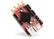
Red Pitaya SIGNALlab 250-12
Red Pitaya SIGNALlab 250-12 is a high-performance signal capture and analysis instrument. The SIGNALlab 250-12 can be used as an oscilloscope, spectrum analyser, and logic analyser, with more applications to be released in the future. The SIGNALlab 250-12 provides real-time processing capabilities and fast analog front and back-end performance. Small and portable, it also offers the benefits of remote access over Ethernet or Wi-Fi®, using Matlab, Labview, Scilab, or Python via the Red Pitaya SCPI (Standard Commands for Programmable Instrumentation) list of commands.
The SIGNALlab 250-12 is based on a powerful Xilinx Zynq® 7020 Dual-Core Arm® Cortex®-A9 CPU and FPGA, with 1GB DDR memory and 1Gbit Ethernet connectivity. It features two-channel 250Msps, 14-bit signal generation, 12-bit signal acquisition, and two-channel 250Msps. Accuracy and quality of the signal are assured with 12-bit ADC resolution, a frequency response of ±0.5 dB up to 45MHz and -3dB at 60MHz, and channel isolation >60dB (DC to 100MHz).
There are two input ranges of ±1V and ±20V. Outputs can generate signals ranging from DC to 60MHz frequency, with output voltage ranging from ±5V for a 50Ω load to ±10V for high impedance loads. The SIGNALlab 250-12 also features software control for attenuators, gain, and trigger level. There is one trigger input via a BNC connector on the front panel and one reference clock input (10MHz) via an SMA connector on the back panel. Signal capture is fast, with rise/fall time of 13ns input 1/20 and 11ns input 1/1.
The SIGNALlab 250-12 features a broad range of interfaces, including Ethernet, USB, SPI, I2C, and 16 GPIOs. The device also boasts four additional slow analog inputs and outputs.
Features
- Xilinx Zynq 7020 Dual-Core Arm® Cortex®-A9 CPU and FPGA
- 1GB DDR3 SDRAM
- Connectivity
- 2x 250Msps in, BNC
- 2x 250Msps out, BNC
- 2x 26 extension connectors
- SPI, UART, I2C
- 16 digital I/O (3.3V)
- Analog in 12-bit
- Analog out 12-bit
- 100/100 Base-T Ethernet, RJ45
- 2x USB-A
- eSATA/USB combo
- USB-C™
- MicroSD slot
- Synchronization inputs
- Trigger input, level SW settable, BNC
- Reference clock input, SMA
- 10VDC to 28VDC input voltage, barrel connector
- 10x user LEDs
- 2x system LEDs
- JTAG interface
- Browser-based GUI
- Linux operating system, bootable from SD card
- 0°C to +55°C operating temperature range
- -20°C to +85°C storage temperature range
- Dimensions
- 110mm x 157mm x 23mm (PCB)
- 131mm x 157mm x 58mm (chassis)
- Input
- 30V maximum input voltage
- AC/DC input coupling, software selectable
- 1MΩ input impedance
- Software selectable voltage range
- ±1V at 1/1
- ±20V at 1/20
- 12-bit ADC
- >60dB channel isolation, DC to 100MHz
- Frequency response
- ±0.5dB up to 45MHz
- -3dB at 60MHz
- Rise/fall time
- 11ns at 1/1
- 13ns at 1/20
- Output
- Max output voltage including offset
- ±5V on 50Ω load
- ±10V on HiZ load
- 50Ω output impedance
- Return loss
- <-30dB at 60MHz
- <-20dB at 100MHz
- x1/x5 output gain, software selectable
- Frequency response (-3dB)
- ±0.5dB up to 45MHz
- 57MHz x5 output range
- 60MHz x1 output range
- Rise/fall time
- <17ns, 50Ω or HiZ load
- Max output voltage including offset
Applications
- Oscilloscope and signal generators
- Spectrum analyzers
- Logic analyzers
- Signal generators
- Science, Technology, Engineering, and Math (STEM) teaching and learning platform
Kit Contents
- Red Pitaya SIGNALlab 250-12 PCB in an aluminum housing
- Oscilloscope probes
- SD card
- Power supply
- USB-A-to-USB-C cable
- Ethernet cable
Board Layout

Block Diagram

On The Board

AMD / Xilinx Zynq®-7000 SoC First Generation Architecture
A flexible platform to launch new solutions while providing a fully programmable alternative.
Related Kits

Red Pitaya STEMLab Ultimate Kit
Contains everything needed to start developing with the Red Pitaya Test and Measurement Boards.

Red Pitaya STEMLab Edu Kit
Contains everything needed to start developing with the Test and Measurement Boards.

Red Pitaya STEMLab Diagnostic Kits
Everything needed to use the board as an oscilloscope, spectrum analyzer, and more.
Red Pitaya STEMLab Starter Kits
Everything needed to start developing with the STEMLab 125-10 or 125-14 test and measurement boards.